Tuesday, 14 June 2011
Reflection on DAB510
Just a quich reflection on my experience with the subject. I have found this subject one of my more favourable over the past two and a half years. In particular, I have thoroughly enjoyed experienced and learning about modular achitecture, as I find it a most interesting branch, comparitively to the different ones we hae learnt over our time at QUT.
Adaptability
Just showing that my module could be used anywhere, here shown as a pergola in a park. But it could be used anywhere for anything.


Sunday, 12 June 2011
Extensions
For more modules to be added to my design, only two steps are necessary. Firstly a bobcat or backhoe can be brought on site, and for each module, four auger footings are drilled. Then the modules are delivered and are simply bolted to the footings via the column feet.


Friday, 10 June 2011


Wednesday, 8 June 2011
Modular Adaption
This is just showing how the module can adapt, showing each manouverable part in different sequences.
This is showing the module without any changes. Soft top roof.

This shows the module with a distorted roof, and one bench raised.

The roof has again changed, and two benches have been raised.

Change to a hard top roof, it is currently angled, two benches are raised, and wall partitions are beginning to be shifted around.

The roof angle has changed again, one bench this time, with one wall completely blocked off.

Closing time, the roof is at its lowest point, and the walls on all four sides shut the module down completely.

This is showing the module without any changes. Soft top roof.


Closing time, the roof is at its lowest point, and the walls on all four sides shut the module down completely.

Site Plans
My site plan expands on my floor plan in the fact that is shows how my design will work on site. I have placed my building where it will stand, then have left an area for where my design can be expanded. I have then developed a system of paths which run through the site, with several building nestled into the cliff.
The first, unseen on this site plan, is a hotel which has already been built, the resides on the far left-hand side of the site. Then I have just placed some proposed buildings, not necessarily in the same form, but to have the same function as what I have shown.
They go in order from left to right, continuing the greater pattern of restaurants, on the left, to clubs on the right. I feel a scaled representation of the greater suburbs would be the best plan for this particular site.
A carpark, taxi-rank and delivery zone occupy the lefthand side of the site, this is because there is the only vehicular access point, and it ties in well with my site planning, as the restauranteers and diners which are situated on the left-hand side are more likely to be driving, where as the patrons of the pubs and clubs would more likely be catching public transport. There is a ferry terminal on the right hand side of the site, as well as bus stops there as well.

Wednesday, 1 June 2011
Floor Plans
My floor plan developed nicely after researching spatial adjacencies and room areas. I wanted to utilize the building already on site, and have used them for the kitchens, and for the toilets. This gives the opportunity to hide the service spaces and to show off the public. Another bonus for placing the kitchen in the building to the left, was there was then an ease of access for deliveries from the only road access.
The design was placed where it is to maximise the best of both worlds with it's surrounds, and to maximise and utilize the only available views from the site, without elevating the building too much.

The design was placed where it is to maximise the best of both worlds with it's surrounds, and to maximise and utilize the only available views from the site, without elevating the building too much.

The restaurant part of the design is placed in between the pilons to take advantage of some of the best views in Brisbane. This is also an advantageous spot for access to the kitchens, which is vital for efficient service.
As when you are going out you are more interested in the people you are with over the views, the bar/pub/club side of my design faces inward toward the cliffs.
The main entrance draws peolpe infrom the main pathway, and the user is led down a short corridor, to a three way option. they are greeted at a welcome area, and can then either proceed to the restaurant, go left to the pub style area, or go right to the bar area.
Materials
Materials for the module are as follows, for the I-Beam section of the columns and sub floor framing, galvanised steel is used so as to avoid rusting, and employ longevity. All timber used on the module is actually faux timber, as researched in an earlier blog entry. This faux timber is made from hemp and biodegradable glue, and has the same properties as timber, but when buried can completely biodegrade within a mere two weeks. The column shell is made of aluminium.
Fibonacci Growth
Fibonacci's formular not only dictates the shape of my module and the area distribution of spaces, but it also influences the overall shape of my design. Fibonacci's curve is not only about forming the perfect rectangle and curve, but is also about growth. Shown in the image below is how my design has been formed and how it grows around the Fibonacci shape.


The centre is the welcoming area, and bar, then it grows around the restaurant, through the kitchens, then envelops the bar area.
Wednesday, 25 May 2011
Fibonacci Sequence and Space Area
For the area floorspace distribution between different spaces, I used the ''Metric Handbook", which has a wealth of information handy for any designer. Having researched the area needed for each different space, I discovered that they matched almost identically with that of the Fibonacci mathematical sequence as well, except with a, extra decimal place, so 1,1,2,3,5,8,13,21 became 10,10,20,30,50,80,130,210. From this discovery I was able to further link my design back to my concept not only by the cure created by this sequence, but with the sequence itself.


Spatial Planning
After completing the technical side of my module design, I began to look at spatial awareness, and how the modules would come together to create the space I want. It would not be good enough for the modules to work individually well, but on a grander scale break down into uselessness.
I began my research by re-researching spatial adjacencies, and bubble diagrams, focusing on what rooms my design would need to function well.

 Going off these spatial diagrams, I can begin to formulate an idea aout how and where the spaces will fit together.
I began my research by re-researching spatial adjacencies, and bubble diagrams, focusing on what rooms my design would need to function well.


Wednesday, 18 May 2011
Walls & Benches/Seats
The sliding walls and benches are an integral function for the adaptability of my module. Both work on a similar roller wheel and rail system, and both are fitted with clamp brakes, so the benches will stay up, and the walls can be locked at night.
Given the seat will need to be able to resist the force of several people sitting on it, four heavy duty rollers have been used at each end, and these roll on a steel rail, which is prefabricated onto the outer casing of the column.

 As the walls will not have the same weight applied to them as the benches, it will suffice to only have two rollers at each end. These also run on similar prefabricated steel rails.

Given the seat will need to be able to resist the force of several people sitting on it, four heavy duty rollers have been used at each end, and these roll on a steel rail, which is prefabricated onto the outer casing of the column.


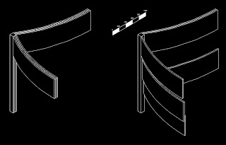
Manouverable Roof, Soft & Hard Top
This was possiby the hardest technically to solve on the module. For the hard roof, if the columns were going to change height, the roof would have to be able to follow accordingly, whilst the distance between columns would increase. I solved this by having a ball joint on the top of the column, and the underside of the roof, with a universal in the middle, so when the columns were changed, the roof would adapt accordingly. Material wise, the roof is made of faux timber, a biodegradable material researched earlier in the semester (see earlier blog post) which is strapped together with stainless steel bars on the outside, for added strength, and looks.


The hard roof is designed to accommodate the wall partitions, and the modules with the hard roof are used on the outside, so the building can be completely shut down when necessary.
The soft roof was a little bit easier, where a canvas with a stretch factor was tied between the columns. the outer edges of the canvas were tied with an aluminium band, so as to keep the shape of the floor. Using a stretchy canvas enable the module to take on some pretty crazy shapes when the columns were changed.


Wednesday, 11 May 2011
Solving Sub-Floor Technical
For my design to work, the I-Beam columns will have to be extremely well supported and fixed at the base, as there can be no bracing anywhere else due to the multiple moving parts. I have decided to have each column bolted to an auger pile. these are driven into the ground, then each module is attached.
 The sub-floor framing is a typical housing sub-floor, and is as follows. The columns are joined by square hollow tubing bearers. these are welded and plate bolted to the column I-Beams. Timber joists are then bolted onto the bearers, at 600mm centres. Finally the floor is nailed or screwed to the joists. A lightweight timber shell is constructed, and attached to the outside, so as to hide all of the construction underneath.


Column Sliding Technical
An integral part of my design was to master a way of making the four outer columns be able to slide, so the roof can be shaped in any crazy way according the the height of each column.
What I have devised is haveing a central I Beam, which is bolted to the sub-floor, then have an aluminium square outer casing, which runs on rollers on the I Beam. This allows for the outer casing to slide up and down.
 The space provided by the outer casing leaves enough room for a hydraulic ram. In my design this can be powered mechanically, via a remote control motor, so the module can be adapted with ease. If the modules were being sold seperately, The ram can be run with a hand powered crank which folds into the column.

This gives the module adaptability to to work in a business style place with the ability to run mechanically, and for the public, in public places to run powered by hand.

What I have devised is haveing a central I Beam, which is bolted to the sub-floor, then have an aluminium square outer casing, which runs on rollers on the I Beam. This allows for the outer casing to slide up and down.


This gives the module adaptability to to work in a business style place with the ability to run mechanically, and for the public, in public places to run powered by hand.

Thursday, 5 May 2011
The Site as an Extension of Esplanade & Valley
I want the site to be an extension of the Riverside esplanade and the Valley, combining the dining cafe areas, and the nightlife to create a site that has multiple uses day and night, and serves the needs of all people around.


Wednesday, 4 May 2011
Module Shape according to Fibonacci
As previously investigated, Fibonacci curves, based on Fibonacci's formular, are considered aesthetically perfect, and also to be functionally perfect. My module design was shaped using this formular and curves, so as to create an aesthetically pleasing shape, but also so that the functionality of the module would be enhanced.
 All edges are curved following the outer Fibonacci curve. This not only creates a good basis for a tesellating shape, but also builds four unique ways of interaction between people within the module. The module addapts for how you stand, where you stand, where you want to sit, how big a group you are in, how much privacy you want, and whether you want social interaction or a private conversation. This is all achieved by curved spaces, sliding benches/seats and sliding walls.

Revisiting Sit Analysis
To kickstart the third assignment, I wanted to revisit some site analysis, and get back to some basics, to gain further insight into the what, when, where and why of the Howard Smith Wharves. I zoned the suburbs surounding the site, and noted what impact these would have, and how the site links to them.
 There are four predominant areas around HSW, these being the CBD in orange, the Fortitude Valley in purple, the Residential in green, and the esplanade in blue. All are very different style zones, and I feel my design should accommodate each of them in some way. My restaurant/bar style design works with these zones well for being able to cater for business people and families during the day and afternoon via the restaurant, as an extension of the esplanade and the CBD, but then also become an extension of the Valley at night with with the bar.


Also for the area to become a favourable place to visit, the site cannot just be home to my design, there should be a few building to create choice, and inturn create a favourable location which will draw people in from all directions. The way the site is laid out, with the CBD being on the left hand side, and the Valley on the right hand side, the buildings should correspond with this and mirror or replicate the wider context on a smaller scale, with cafes and restaurants to the left, and pubs, clubs, and bars to the right. I have situated my design in the middle, as it incorporates all context.
Monday, 2 May 2011
Modular Design
Each edge of the module works on a sliding mechanism, and come out of the floor to create benches and seats as required.


These images show the adaptability of the module, predominantly the base being able to slide up and down up to 400mm, and the wall partitions sliding down from the roof, 500mm in height.

These four modules show the wall partitions in different sequences. The modules can be joined together to any number of ways and shapes to create unique spaces. Each partition has a separate slide rail, so they can slide past each-other and create any barrier desired.
Saturday, 30 April 2011
Modular Design
I have designed the modular design to be as addaptable as possible. The design does not have set walls, but partitions that can descend from the roof on sliding rails, in 500mm heights to create spaces within each module. The base can also rise and fall on a sliding system so as to create a differentiation between spaces by elavational distinction. The modules when joined together can be used together in any number of possibilites. From one to infininity can form spaces as needed.


Friday, 29 April 2011
Under and Between Story Bridge Pylon
A very unique and pliable space is created under the pylon of Story Bridge. Personally I would find it foolhardy to avoid this space, as it could become a feature point of any design. I have designed a private seating area uder it that has no roof, but is fully sheltered, and open to the beautiful views across the river and city. I have chosen to attach the main bar and serving area to this location, and it will form the central location from which modules and be attahed.


Wednesday, 27 April 2011
Initial Designs
Looking at functionability, I have found that this shape works exceedingly well in two main areas, firstly it is a perfect modular design, able to tessellate at 90 and 180 degrees, giving a broader range of design shape. Secondly this shape opens up four distinct seating arrangements where three to four people can interact in different ways. This gives groups the opportunity to decide where and how they would like to interact, and also gives the opportunity for groups of one to two people the option of either mingling with groups or privacy should they so wish.
This picture shows just a few simple examples of how groups could interact with eachother, but the space would not usually have up to twelve people in it.

This picture shows just a few simple examples of how groups could interact with eachother, but the space would not usually have up to twelve people in it.

Wednesday, 20 April 2011
Brief
Project 2
Modular Learning
Concept:
To utilize the efficiency of curves to develop architectural spaces. Curves can be found everywhere, not only in the built environment, but also in nature, and it instrumental to understand and develop these shapes and incorporate them into design to create successful spaces and solids.
Project 2 builds on from the folie, but will embrace a more in-depth research to develop and grow from a mere activator of space, to a fully functional building which incorporates the site. Project 2 will also develop the idea of Modular Architecture, and will reply to the following briefs:
1. How will the building develop day to day
2. How will the building develop over a timeframe of 20 years
3. Who will use the space
4. How will the form adapt to changes in circumstances
5. How will the form change
6. What will happen to the building after it’s shelf life
Using the efficient and broad range of curves to create a Modular Café and Bike stop area which can morph into a bar at night, making the Howard Smith Wharves not just a thorough-fare, but a destination. Giving meaning to the nigh on abandoned historic area hidden beneath the iconic story bridge. The built form morphs over the short term, and becomes biodegradable in the long term to conform to the needs of modular architecture. The design reflects not only its site’s context, but the broader context of greater Brisbane.
Included Spaces:
1. Café/Bar serving area
2. Seating Spaces
3. Group Spaces
4. Bike Stop
5. Ablutionary Spaces
6. Multiple Entrances
7. Congregational Areas
Tuesday, 19 April 2011
Fibonacci Curves are Everywhere
http://www.youtube.com/watch?v=jiMmWnHpFyU
Looking at curves in nature that work successfully, Fibonacci's curve formular is apparent. Fibonacci's formular is aesthetically pleasing in curves and rectangles, and from these two shapes, almost any aesthetically pleasing shape can be derived.
The attached video goes through and thouroughly explains Fibonnacci's curve and formular, and how it is present in everything in the world around us.
(Accessed 15/04/11)
Curves + Design
http://www.topboxdesign.com/t2-dublin-airport-in-dublin-ireland/
http://www.topboxdesign.com/centre-for-science-and-computation-in-annandale-on-hudson-united-states/
Both of these buildings utilize the efficiency of curves, and successfully incorporate them into design. The curves are used to maximise seating, create efficient flow throughout the building, and for gathering focal points. In the case of Dublin Airport, curves are also used on the roof, for controlling what light enters the building.
(Accessed 12/04/11)
Wednesday, 13 April 2011
Design Concepts


I have been studying human patterns of movement, and have arrived at a few conclusions. In social situations, I have found people tend to move in groups of 3-9, with small groups of 1-2 moving in between. To incorporate this into my design I have been designing spaces that accommodate two to three groups, all linking to other spaces.
A second study of human pattern revealed information about the shapes of spaces and seating to accommodate different variants of groups. curves, both inverted and extroverted seem to be the most accommodating, with varying curves used to create unique spaces.


Subscribe to:
Comments (Atom)